Neocircuit setup
What is NeoCircuit?
NeoCircuit is a sophisticated multi-dimensional optimization tool which is included with the Cadence software available at ISU. According to the company's datasheet for the software:
- Cadence® Virtuoso® NeoCircuit performs automatic circuit sizing and optimization for custom digital, RF, and mixed-signal circuits. Integrated with the Virtuoso custom design platform, Virtuoso NeoCircuit leverages the Virtuoso Schematic Editor and employs the designer’s simulator of choice to size, bias, and verify circuits interactively with a manual starting point or automatically without any starting point.
The root directory for the Neocircuit tool at ISU is /usr/local/cadence/neockt/tools/NeoCircuit. Inside this directory there is a ./docs which contains basic documentation for setting up and using the tool. Initial setup can be performed as follows:
Initial Setup
- Add the following directory to your unix PATH:
/usr/local/cadence/neockt/tools/NeoCircuit/bin - The following definition must also be added to your shell environment:
NEOCKTHOME=/usr/local/cadence/neockt/tools/NeoCircuit - Add these to your terminal environment so they are loaded every time you log in. If you use the bash shell (as suggested by the Cadence setup tutorial) then this can be done by modifying
~/.bash_profile. - Add the following line to your ~/.cdsinit file (if you don't have a ~/.cdsinit file, them make one at this point):
(let () load(strcat(getShellEnvVar("NEOCKTHOME") "/bin/NeoCircuit_cdsinit.il"))) - Before you can access NeoCircuit graphically, you must reload your UNIX environment (you can do this by logging in and out again), then run icfb as you normally would.
Configuring NeoCircuit
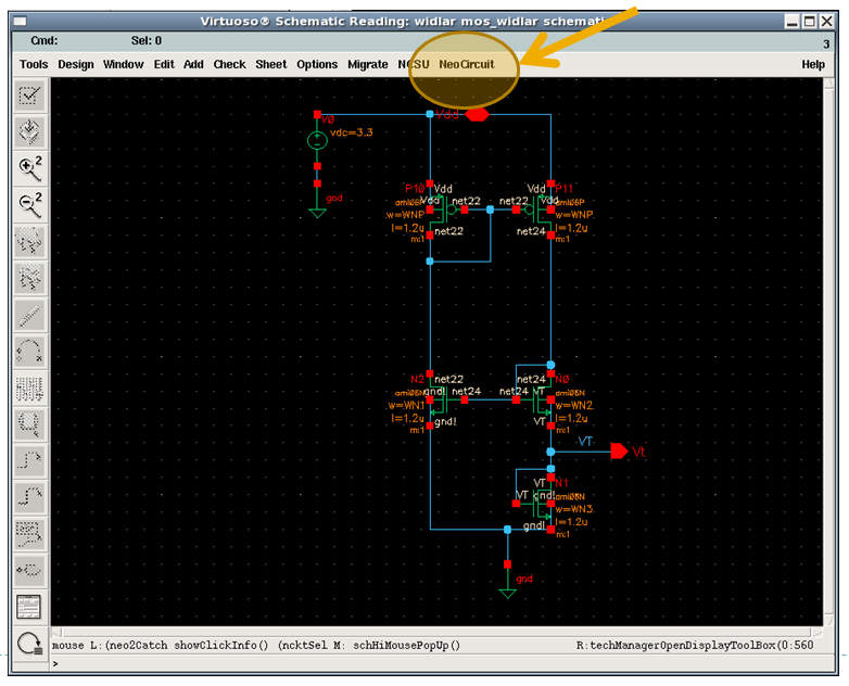
Open a schematic and you will notice a new menu item on the toolbar, as shown below.

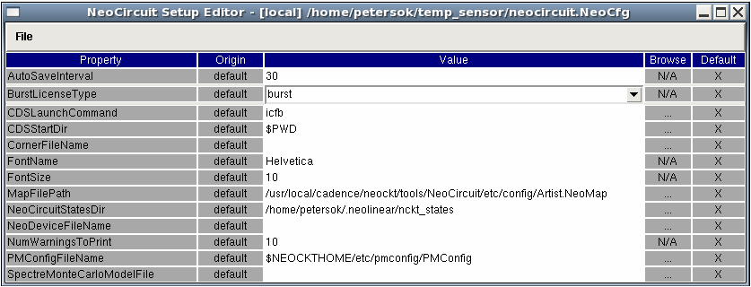
From this toolbar, open ‘NeoCircuit Setup…’ and check your configuration to make sure it’s OK. This is what mine looks like:

If you get an error about not having a configuration file, try running ‘neosetup’ from the command line first. Before proceeding, your configuration should match the image above. Save it as neocircuit.NeoCfg in the directory ~/.neolinear/
Using NeoCircuit
There are two ways to use this tool. The first is to interface directly with your ADE and optimize by adjusting parameters which are already defined as variables. NeoCircuit can also interface directly with the schematic and make alterations there, but this requires a special neodevice file. Unless you are using gpdk180 (the generic 180nm PDK offered by Cadence), you probably do not have such a file. Thus the following steps describe how to use the first method:
- In the schematic you wish to optimize, parametrize any variables (sizing, bias, etc.) that correspond to degrees of design freedom
- If the relationship between two parameters is known (e.x. a current mirror where W1=W2) then parameterize in a way that reflects this. The following image shows a schematic which has been set up in this way:

- Set up ADE as you would to test the circuit, defining variables for each of the parametrized design values
- Make sure you have an 'output' defined which corresponds to the cost function(s) that you will optimize. This must be a single value for each simulation run rather than an array.
- Verify that your simulation works (i.e. the outputs are evaluated etc.) and save the ADE state
- Now choose ‘Launch Neocircuit…’ from the NeoCircuit menu on the schematic. A dialog will appear like the one pictures below.

- From the ‘Setup’ menu in NeoCircuit, choose ‘Constraints from ADE…’ to extract your variables from the ADE state you saved. A dialog will appear like the one below.

- Browse to your saved ADE state and click ‘OK’. The percentage can be chosen arbitrarily since we are going to manually define the range to test.
- Now, under the ‘Variables’ pane of NeoCircuit, you can change the variable ranges that you are interest in exploring. They have the format (min value):(grid size):(max value) as shown below.

- The simulation settings can also be loaded from your saved ADE state. Under the simulations pane, click on Testbench View, and browse to your ADE state. Then click on ‘Get Outputs’ which will run a simulation and find all the resulting outputs.
- Under ‘Output’ you should be able to find the cost function you defined in ADE; click the check mark so that NeoCircuit imports this output from the ADE.
- Click ‘Apply’ to save the simulation profile

- NeoCircuit can help optimize designs with many constraints and goals that need to be met or balanced. In the screnshot below, I have one simple cost function.

- Change the configuration for your cost function to match your optimization goal: in this case, I am trying to minimize the maximum temperature error of a temp sensor and I would like to get it as low as .1C
- From here, there are many different ways to optimize, take data, and visualize relationships, explore sensitivities, etc. Please investigate these functions and add to this tutorial!